

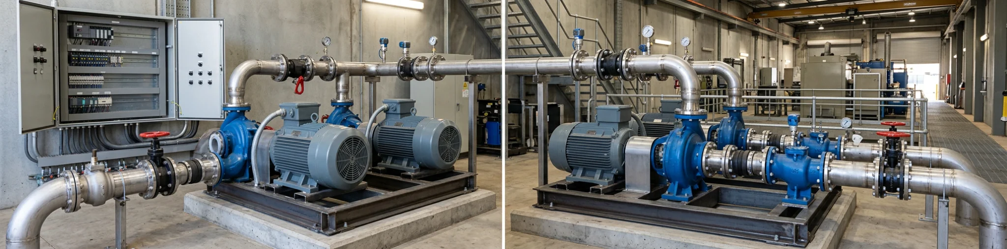
When a pump stops, the first question is not whether another pump is installed. It is what happens to the process, building, site or people relying on that flow. A brief loss of water transfer may be manageable in one application, while a pressure loss, overflow risk or interrupted process can have far greater consequences in another.
That is why duty and standby pump systems need to be planned around operating cases, rather than counted as pumps on a skid. The arrangement should make clear what the system must achieve during normal demand, peak demand, a pump failure and planned maintenance. It should also show who or what transfers the work when conditions change.
The starting point is to separate the pump roles from the hardware around them. In a small arrangement, single and dual pump controls can provide level or pressure control for one or two pumps. The required logic, alarms and transfer sequence still need to be defined for the particular service.
This guide helps consultants, contractors, facility managers and project teams frame that decision. It focuses on the failure cases that shape resilience, without assuming that one configuration or one control approach suits every critical application.
Start With the Consequence of Lost Flow
The term “critical” should describe a service consequence, not simply a preference for extra equipment. Before selecting the number of pumps, define what happens if the required flow or pressure is not available. Consider the immediate effect, the time available to respond and the conditions needed to return the system to service.
For some critical pump applications, the issue may be a loss of pressure to downstream equipment. For others, it may be an inability to transfer water, maintain a level, remove accumulated water or support a process. The same physical pump arrangement can therefore be adequate for one duty and inadequate for another.
Document the consequences in practical terms:
- What service is lost if the active pump stops?
- How quickly does the consequence become unacceptable?
- Can demand be reduced, stored or redirected while the issue is addressed?
- Is an operator present, or must the system respond without immediate intervention?
- Does a planned shutdown create the same consequence as an unexpected failure?
Those answers become the basis for hydraulic capacity, pipework isolation, electrical supply, control transfer and proving tests. They also prevent a common mistake: treating an additional pump as a complete resilience strategy when a common pipework, switchboard, sensor or power fault could still stop the service.
Assign Duty, Assist and Standby Roles Before Choosing a Sequence
Clear role definitions make the expected response easier to specify and test. Sydney Water’s pumping-station design specification, for example, defines a duty pump as the main pump intended to provide the required flow and pressure for most operating time. It defines an assist pump as one that adds performance when the duty pump cannot meet the requirement alone. A standby pump is a matched backup in that specification, available when another pump is offline or fails and sometimes used through automatic rotation.
These definitions are useful planning language, not a universal design rule. The required number of standby pumps and their capacity depend on the project’s criticality, the consequence of supply loss, pump size, maintenance approach and resilience requirements.
Duty Pump: The Normal Operating Role
The duty pump carries the ordinary demand case. Its selection begins with the required flow, pressure or head, fluid conditions and expected operating range. It must be assessed as a pump operating in a system, not as an isolated item with a nominal capacity.
The duty role should also identify how normal operation is recognised. A level, pressure or flow signal may call for pumping, but the actual starting and stopping points, permissives and alarms are part of the application design. Where the control requirement needs additional visibility or communication, advanced dual pump controls publish data logging and ModBus communications as additional features. That does not establish the control philosophy for every site.
Assist Pump: Capacity for a Defined High-Demand Case
An assist pump is not merely an extra pump waiting for trouble. It is assigned a normal operating purpose: joining the duty pump when demand exceeds what the duty pump is expected to provide alone. The trigger must be based on the actual system condition, such as a sustained pressure or level response, not an assumption that a second pump will always improve the result.
Parallel pumps do not automatically deliver twice the flow of one pump. The combined operating point depends on the system curve, which represents the head the pipework and connected system require as flow changes. The pump curves, the control sequence and the operating region all need review at the relevant case.
Standby Pump: Recovery From an Unavailable Role
A standby pump exists to take over when a duty or assist role is unavailable. It may be held ready until a fault occurs, or the assigned roles may rotate so that the pumps share operating exposure over time. Either way, “standby” should not mean unexamined. A pump that has not been proved with its own valves, controls and protection path may not provide the recovery assumed on a drawing.
Capacity should match the failure case, not a label. If one duty pump must maintain the full required service after another pump fails, the standby arrangement needs to support that stated case. If a reduced service is acceptable for a defined period, the brief should say so explicitly. Product navigation can help the project team survey available pumping equipment, but it cannot define the required duty or resilience case.
Walk Through the Operating Cases That the System Must Survive
The most useful architecture review is a short set of scenarios. Each scenario should identify the hydraulic outcome required, the control action expected, the isolation state and the evidence that the response occurred. The cases below are a planning framework, not a substitute for project-specific design, manufacturer information or applicable compliance review.
Normal Demand
Under normal demand, identify the active pump role, the expected flow and pressure range, and the signals that start and stop the pump. Check the pipework route, non-return arrangement and manufacturer-defined operating limits. State what counts as a fault, including an inability to maintain pressure, an abnormal level trend, loss of a permissive or a failed sensor.
Peak Demand
Peak demand is the case that justifies an assist role, where one is required. Define whether the active duty pump remains running while the assist pump joins, what condition calls the assist pump and what condition allows it to stop again. Consider whether the combined flow passes through shared pipework, valves, filters or other components that may limit the result.
This is also the point to check that the system will not cycle pumps unnecessarily as demand fluctuates. The correct settings and delay logic depend on the hydraulic response, pump curves and operating risk. They should be set from the project requirements, not copied from another site.
Pump Fault
For a pump fault, the key question is not simply “does the standby start?” It is whether the available pump can take the required role without being blocked by the failed pump, a closed valve, a common suction condition or an unsuitable control state.
Specify the response in order:
- How is the fault detected and latched for operator review?
- Which pump is called next, and under what permissives?
- Which isolation and non-return arrangements allow the alternate pump to operate?
- What alarm, indication or communication is needed for the people responsible for the site?
- What condition confirms that the alternate pump has restored the required service?
This sequence is more useful than a generic redundancy claim because it exposes shared points of failure. It also makes clear whether the design calls for full service restoration, a reduced operating mode or a controlled shutdown.
Planned Maintenance
Planned maintenance deserves its own case. A system might respond well to an unexpected motor fault yet be difficult to isolate, drain, inspect or return to service without interrupting the remaining pump. Access, lifting arrangements, isolation valves, bypasses and safe work planning all affect how practical the standby concept is.
Define the maintenance state before construction: which pump can be isolated, which pump becomes active, how the controller is informed, and what test is required before the maintained pump returns to its available role. The goal is not to prescribe a maintenance interval. It is to ensure the architecture allows maintenance without relying on an informal workaround.
Once these operating cases are defined, APT Water can be used as a neutral navigation point for current pump, control and packaged-system categories. The selected architecture must still be assessed against the project’s hydraulic, control, isolation and resilience requirements.
Power or Control Fault
Pump availability can be lost without a hydraulic or mechanical failure. A local power issue, failed control component, damaged signal cable, incorrect mode selection or shared switchboard problem can affect more than one pump. For critical pump applications, list the common components that could defeat both roles and agree the power, manual-operation, sensor, alarm and communication requirements with the appropriate disciplines.
Turn Scenarios Into Hydraulic, Control and Isolation Requirements
Once the cases are written, convert each one into requirements that can be checked. This is the step that connects a resilience intention to a workable pump system.
Hydraulic requirements. Record the flow and pressure or head required for normal service, peak demand and the defined failure state. Confirm the pump and system curves at each relevant operating condition. For a suction-limited installation, the available net positive suction head must be assessed against the manufacturer’s required value at the applicable duty. The necessary margin is application-specific and should follow current manufacturer and project requirements.
Control requirements. State the start, stop, assist and transfer conditions in plain language before selecting detailed programming. Identify the process signals, permissives, fault recognition, alarm priorities and the confirmation needed after a transfer. Do not assume that a dual-pump controller includes every alternation, alarm, remote monitoring or failover function.
Isolation requirements. Show how one pump can be removed from service without unintentionally preventing the remaining pump from operating. Include the valves, non-return paths, common headers and any source or discharge constraints that affect the scenario. Isolation also needs to be operable and identifiable by the people maintaining the system.
Access and return-to-service requirements. Identify what must happen after a pump is repaired or inspected. A clear sequence for restoring valves, controls and the normal role reduces the risk of leaving an otherwise healthy pump unavailable.
The arrangement may ultimately be delivered as discrete equipment or as part of a packaged solution, but the architecture should be settled first. A published Perth Children’s Hospital pump-system case study describes triplex and duo booster and hot-water circulating pump sets with Hydrovar controllers. It is a specific project example, not evidence that the same configuration or outcome suits another critical service.
Prove the Handover Instead of Assuming It Works
The final test of duty and standby pump systems is evidence that the stated roles transfer under controlled conditions. Commissioning and maintenance plans should be based on the agreed scenarios, with tests performed safely by qualified personnel and within the project’s procedures.
For each relevant case, record the initial condition, the action introduced, the expected response and the result. A practical test schedule may cover:
- normal duty start and stop response;
- assist-pump call and return to normal demand;
- simulated or controlled duty-pump unavailability, where appropriate;
- standby-pump start, required hydraulic response and alarm indication;
- isolation of a pump for planned maintenance;
- restoration of the pump and confirmation of its available status; and
- the effect of agreed control, signal or power fault simulations.
The evidence should be proportionate to the application. It may include records of pressure, flow, level, run status, alarms or control states, depending on what proves the required service. The purpose is to show that a transfer has occurred and that the resulting operating condition matches the resilience brief. It is not enough to show that a motor started.
Testing also reveals where instructions need to be clearer. Operators and maintainers should be able to identify the current pump roles, understand the indication of an unavailable unit and know when a fault requires escalation. Any final procedures should align with the installed equipment, current manufacturer documentation and site safety requirements.
Build a Resilience Brief Before Requesting a System
A concise resilience brief gives the project team a better basis for selecting equipment and defining controls. It should state the application without assuming a particular pump model or a universal standby ratio.
Include the following information:
- service supplied and the consequence of lost flow or pressure;
- normal demand, peak demand and acceptable reduced-service cases;
- duty, assist and standby roles required for each scenario;
- source, discharge, fluid properties and hydraulic duty information;
- expected operating range, pump curve review and suction conditions where relevant;
- available power, control signals, alarms, communications and manual operating needs;
- pipework, valve, header and isolation arrangement;
- access and maintenance constraints; and
- the handover tests and records needed to prove the agreed response.
This approach avoids treating spare capacity as a promise of availability. It asks the more useful question: what service must remain available, under which failure or maintenance condition, and what evidence will show that the system can respond?
Frequently Asked Questions
What Is the Difference Between Duty, Assist and Standby Pumps?
A duty pump provides the required service for most normal operating time. An assist pump joins when demand exceeds what the duty pump can provide alone. A standby pump is available to take over when another role is unavailable. The exact roles, capacity and sequence should be set by the project demand and resilience requirements.
Does a Standby Pump Need the Same Capacity as the Duty Pump?
Not always. It depends on the service required after a failure or during maintenance. If the system must maintain the full duty with one pump unavailable, the standby arrangement must support that case. If a defined reduced service is acceptable, record the limit and duration in the resilience brief rather than assuming a standard capacity.
Do Two Pumps in Parallel Double the Flow?
No. Pumps operating in parallel interact with the system curve, so the resulting flow depends on the pipework and system resistance at the combined operating point. Review the relevant pump curves and operating limits for the expected demand case.
How Often Should Duty and Standby Roles Alternate?
Set the alternation frequency and logic to suit the controller, pump manufacturer guidance, operating risk and maintenance plan. Rotation can help share operating exposure, but it must not conflict with the required availability, testing or process sequence for the site.
Define the Required Response Before Selecting the Arrangement
Effective duty and standby pump systems begin with a clear account of normal demand, peak demand, pump unavailability, maintenance and control or power faults. The architecture then follows from the required hydraulic service, isolation path, transfer logic and evidence tests.
Prepare the operating cases and resilience brief before comparing equipment. When you are ready to turn those cases into a project discussion, discuss the required operating cases with APT Water or call +61 8 6143 1000.