

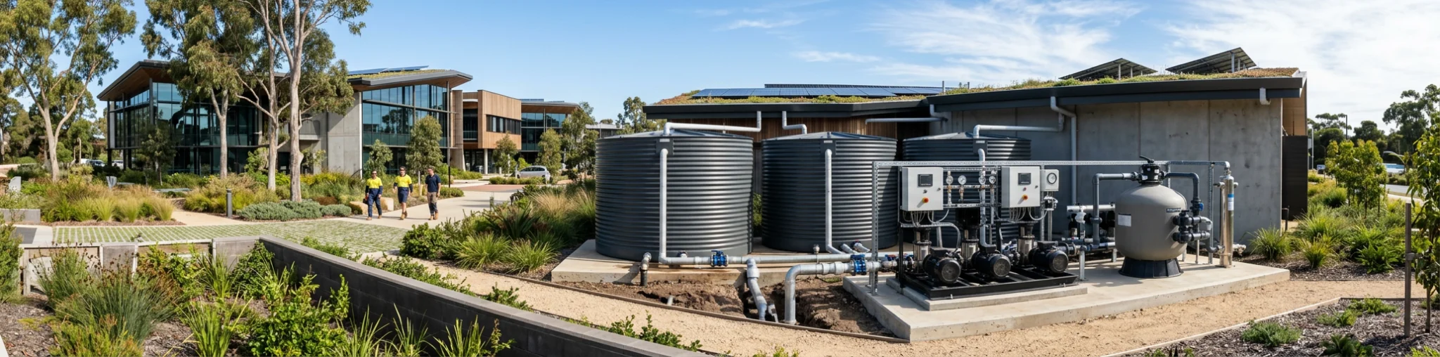
Roof area and tank invert are locked before the hydraulic drawings hit the bench, and the job is still to make pressure at cisterns, solenoids and wash-down points. Rainwater reuse pumps die from short cycling, air ingestion and a duty that ignores how empty the tank runs in a dry spell. We size these systems for available storage, residual head and a control method that does not hammer the start contactors. Our packages include suction protection, break-tank logic where needed, and a curve that still works when the tank is low. Undersize the set and fixtures starve; oversize it and the pumps cycle to scrap.
Fixture Demand Comes Before Tank Size
Start with the non-potable outlets, not the 50 kL tank the architect drew. Count the dual-flush cisterns, the urinals, the hose cocks and the irrigation zones that will actually run at the same time. A typical three-storey commercial block in the metro area can pull 2.8 L/s just from toilets during a morning peak; add two irrigation stations at 1.4 L/s each and you are already looking at 5.6 L/s before anyone opens a wash-down tap. That peak is what sets the duty of the commercial rainwater harvesting pumps, not the average daily volume.
We convert those fixture units into a simultaneous flow using the same diversity you already apply on potable work. Then we add 15 percent for the filtration back-wash and the small losses through the first-flush diverter. The number that comes out is the flow we design the impeller around. If you only give us tank volume we will still ask for the fixture schedule, because a 100 kL tank feeding three toilets is a completely different pump set from a 20 kL tank feeding a 4 000 m² warehouse roof and a cooling-tower make-up line.
Once the peak flow is locked we look at the residual pressure the hydraulic consultant has nominated at the furthest cistern. Most commercial specs want 150-200 kPa at the fixture. That residual, plus the static lift from the wet-well water level to the roof plant, plus the friction in the rising main you are about to hang, becomes the total head. We do not guess the friction; we use the pipe size and the equivalent length you already know from the site set-out.
How Much Rain Actually Reaches the Wet Well
A 3 200 m² metal roof in the Perth metro area looks generous on paper. After first-flush, gutter losses and the fact that most of our rain falls in four winter months, the reliable yield is closer to 1 400 kL a year, not the 2 200 kL a simple 0.8 runoff coefficient suggests. We run the monthly rainfall files against the roof plan you supply so the storage and the pump duty stay matched to what actually arrives.
The first-flush chamber has to be sized so it does not starve the wet well on a 15 mm event. We normally allow 0.5 mm of roof area for the diverter on a reasonably clean commercial roof; more if the site is next to a hardstand that throws dust. That volume never reaches the pumps, so it comes off the yield calculation before we talk tank size. The same applies to the overflow weir: once the tank is full the extra water leaves the system and the pumps see only what is stored.
You already know the roof will not be perfectly clean. Leaf guards help, but commercial sites still send grit, bird droppings and the occasional screw into the downpipes. That load sits in the wet well and will find the impeller unless we put a strainer and a 100-micron filter on the suction side. We size the filter surface so the pressure drop stays under 20 kPa at peak flow; otherwise the NPSH you thought you had disappears.
Storage and Wet-Well Volume That Stop Short Cycling
A pump that starts every ninety seconds will not last the defects period. We size the live storage above the pump cut-in so the run time at the lowest VFD speed is at least three minutes. On a duty/standby pair that usually means 800-1 200 litres of usable volume in the wet well or the tank outlet chamber, depending on the cut-in level you can live with.
If the architect has already locked a slimline tank against the boundary, we tell you early that the live volume is too small and we will need a larger break tank or a VFD with a sleep function that holds pressure without cycling. We would rather change the tank drawing now than watch you pull a burnt stator in month eleven.
The wet-well floor needs enough fall and a sump so the last 150 mm of water does not sit as sludge. We set the pump intake 200 mm off the floor and leave an annulus around the shroud so you can still get a camera or a desludging hose down there in five years. That annulus is part of the NPSH calculation; ignore it and the pump will cavitate on a hot January afternoon when the water level is at its lowest.
Duty Point, Rising Main and the Head You Actually Have
The duty we stamp on the curve is the peak flow at the total head that includes your rising main. We ask for the pipe material, the internal diameter and the number of bends you already know from the trench. A 63 mm PE rising main that looks fine on a 30 m run will eat 80 kPa once you add the valves and the water-meter assembly the hydraulic consultant forgot to draw.
Static head is measured from the lowest water level in the wet well (pump cut-out) to the highest fixture, not from the tank overflow. We add the residual the spec calls for and then 10 percent for ageing of the pipe and the filter. That is the head the impeller must make at the flow you calculated from the fixtures. If the number comes out at 48 m we do not pick a 50 m pump and hope; we pick the next curve that still has 15 percent spare at that point so the VFD can turn down without falling off the end of the curve.
NPSH available is calculated from the atmospheric pressure, the vapour pressure at 25 °C (we use summer water temperature), the static height of water above the impeller and the friction in the suction pipe and strainer. On a typical underground wet well that NPSHa is often only 3.5-4.2 m. We select a pump whose NPSHr is at least 1 m below that figure at the duty flow. If the wet well is shallow we tell you to drop the pumps or raise the cut-out; we do not leave you with a set that will rattle itself apart.
Packaged Sets on a Skid Versus a Station Over the Wet Well
When the wet well is already poured we drop a complete packaged set on a hot-dip galvanised skid that you can crane onto the slab in one lift. The pumps, the manifold, the VFD panel and the pressure transducers are already piped and wired. You only make the rising-main connection and the power feed. We build those fabricated pump systems to the duty we calculated from your fixture schedule so the only site work left is alignment and commissioning.
If the collection chamber is still in the ground we fabricate a complete pump station that becomes the wet-well lid and the headworks in one piece. The pumps hang on the guide rails, the valves sit in a dry valve chamber, and the controls are already mounted. You can see the range of fabricated pump stations we already run on similar commercial roofs; the wet-well diameter and the incoming pipe invert are the only dimensions we need from you to lock the drawing.
Either way the column, the shroud and the intake strainer are sized so you can still pull a pump without draining the entire tank. We leave lifting points and an access hatch that matches the confined-space procedure you already use on site.
Controls, VFDs and the Changeover You Will Actually Use
A single-speed pump on a commercial rainwater reuse system will either short-cycle or run out on the end of the curve when only two cisterns are flushing. We put a VFD on the duty pump and a second VFD or a soft-starter on the standby so the set can track the demand from 30 percent up to peak without hunting. The pressure transducer sits on the discharge manifold after the non-return valves; we set the PID so the pump sleeps at 400 kPa and wakes at 320 kPa. That band stops the rising main from hammering when a bank of cisterns fire together.
When the tank level hits the low-level probe the controls open the mains solenoid and close the rainwater isolation valve. We use a delayed changeover so the cisterns do not see a pressure dip. The same panel logs run hours and starts so you can see which pump is doing the work before the next service. All of that is already programmed when the skid leaves our workshop; you only set the cut-in and cut-out levels to match the probes you installed in the wet well.
APT Water also leaves a dry contact for the BMS so the facilities manager can see tank level and pump status without walking to the plant room. That contact is cheap insurance against a call-out at 2 a.m. because someone thought the rainwater had failed when it was only the irrigation controller that had stuck on.
Filtration and the Annulus You Leave for Later
Commercial roofs send more grit than a house roof. We put a 2 mm strainer on the pump intake and a 100-micron automatic filter on the discharge before the water reaches the rising main. The filter is sized so the pressure drop at peak flow stays under 15 kPa; otherwise the extra head comes straight off the NPSH margin we calculated. The filter has its own back-wash line that returns to the wet well or to waste, depending on what the site permit allows.
We leave an annulus around the pump shroud and a clear space beside the rising main so you can still get a camera or a desludging lance down the wet well in year five. That space is drawn on the station drawing we issue; it is not an afterthought. If the wet well is circular we keep the pumps offset so the sludge can still migrate to the sump rather than sitting under the intake.
Permaglass column is not usually required on a rainwater station, but the same principle applies: we specify a material that will not corrode in the slightly acidic water that comes off a metal roof, and we leave enough clearance that you can still pull the set without cutting the lid.
What the National Construction Code Already Requires
Non-potable rainwater that supplies toilets and irrigation is still plumbing. The pipe marking, the backflow prevention and the air-gap or reduced-pressure-zone device at the mains changeover all sit inside the National Construction Code. We design the valve arrangement and the labelling so the certifier can sign it off without a second visit. You already know the lilac pipe and the “rainwater” tags; we just make sure the pump station drawing shows them in the right places.
The same code sets the overflow and the first-flush requirements that affect how much water actually reaches the wet well. We take those volumes off the yield calculation before we size the pumps, so the set you hang is not oversized for a catchment that never quite fills the tank.
The Drawings We Need From You
Send the roof plan with downpipe locations, the tank or wet-well invert, the fixture schedule and the rising-main route you already have in the ground. We will come back with a duty point, an NPSH check and a skid or station layout that matches the excavation you can actually do. That is the only next step that matters: get those four items to us and we will seize the rainwater reuse pump systems so you can hang the column and walk away knowing the commercial rainwater harvesting pumps will still be running when the defect period is over.
Once the roof plan, tank invert, fixture schedule and rising-main route are across, discuss rainwater reuse solutions, then size the reuse set to the excavation you can actually do.