

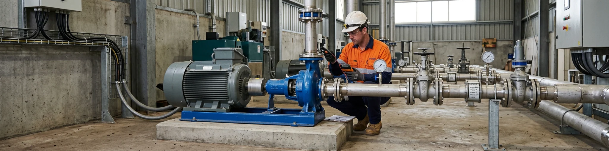
A newly installed pump set can look complete while important conditions remain unchecked. A drawing may have changed during installation, pipework may be carrying stress into the pump, or a control signal may not reflect the intended operating sequence. Starting the equipment before those details are resolved can turn a manageable commissioning issue into damage, rework or an unclear handover.
This pump commissioning checklist provides a practical hold-point sequence for new pump systems. It is not a substitute for the project commissioning plan, current manufacturer instructions or the qualified people responsible for mechanical, electrical and control work. Its purpose is to help the project team confirm what must be released, observed and recorded before the system moves to operational handover.
The sequence suits water-transfer, pressure-boosting, irrigation, drainage and process-water installations, but the detail will change with the equipment and duty. The original pump-system design factors should still be traceable at commissioning, because they explain what the system was intended to do.
Gate 1: Confirm the Approved Documents and Duty Basis
Commissioning begins with a shared version of the intended duty, not with the start button. Gather the current manufacturer installation, operation and maintenance instructions, approved drawings, control documentation, pump curve information and project-specific commissioning requirements. Confirm that the documents identify the installed equipment and any changes made after design or procurement.
The duty basis should state the operating case being checked. That may include the required flow, expected head or pressure, source and discharge conditions, fluid details, control mode, and duty or standby arrangement where applicable. It also needs the assumptions that affect those values, such as tank levels, valve line-up for the test, pipe routes or upstream conditions. A measured result cannot be meaningfully compared with an unstated condition.
Do not treat a catalogue maximum as the target. For a centrifugal pump, the operating point is where the system demand and the applicable pump curve meet. The correct curve, speed and configuration must be identified before the team decides whether an observed pressure or flow is expected. This is especially important where a variable speed drive, parallel pump arrangement or changing source level affects the operating condition.
Evidence output: a controlled commissioning pack containing the current IOM, approved duty record, relevant curve, drawings, cause-and-effect or control narrative where fitted, and a list of open design or installation changes.
Gate 2: Release the Installation and Mechanical Work
Before a pump is run, inspect the installed assembly against the manufacturer and project requirements. The foundation, baseplate or support arrangement needs to be sufficiently rigid for the specific unit. Check that the unit is secured as required, guards are in place where required, and access is available for the inspections and maintenance tasks described in the IOM.
Pipework requires the same attention. It should be independently supported so it is not forcing the pump connections into position. Misaligned flanges or unsupported piping can transfer load to the casing, disturb alignment and contribute to damage. The answer is not to pull pipework into place with the pump flanges. Resolve the pipework condition first, then verify the connection and alignment using the applicable manufacturer procedure.
Coupling alignment is a manufacturer-specific check. It must be checked to the required specification, including after relevant piping is connected or after work that could have affected the machine position. Do not insert a generic alignment tolerance into a project record. The correct value depends on the equipment and instructions in force for that installation.
Also check practical details that can complicate a first run: fasteners, lubrication or seal arrangements where applicable, drains, vents, instrument tappings, guards, labels and safe access. A packaged arrangement may bring pumps, pipework and controls together, but commissioning still needs to confirm the actual installation. Where the project includes packaged pump systems, use the supplied documentation to identify the boundaries between package checks and site-interface checks.
Evidence output: completed mechanical inspection record, alignment result against the applicable specification, installation photographs where required, and an open-items list for anything not ready for release.
Gate 3: Release Electrical, Controls and Safety Functions
Electrical and control checks must be performed by authorised, competent personnel under the project safety arrangements. The commissioning team should confirm the evidence, not attempt live electrical work outside its authority. That includes confirmation of the correct supply, protection, earthing, motor data, isolation arrangements, control-panel configuration and any required permits or safety documentation.
Review the intended control sequence before an operational start. Identify the selected mode, such as local or remote control, automatic duty changeover, level or pressure response, permissives, interlocks, trips and alarm reporting where they are fitted. The purpose is to make sure the observed response can be judged against an agreed sequence rather than against assumptions made at the panel.
For a three-phase motor, rotation must be checked before full operation in accordance with the manufacturer and site procedure. If rotation is wrong, authorised electrical personnel must correct it. Do not treat a brief rotation check as a universal method or give unqualified people instructions for changing connections. The correct approach also depends on the pump, motor, coupling arrangement and commissioning controls.
At about this point, a clear record of the system boundary becomes valuable for every party involved. Product and system information can help frame a Western Australian project, but the project team remains responsible for applying the current manufacturer documentation and project requirements to the installed system.
Evidence output: electrical release confirmation, control and alarm test record, documented rotation check, and any authorised change record for settings or wiring.
Gate 4: Establish Hydraulic Readiness and Prime
Hydraulic readiness is more than confirming that there is water nearby. Check the source and discharge conditions that apply to the planned start, including expected liquid levels, available suction conditions, pipework readiness and the condition of any strainers, valves or other components that affect the test path. The team should use the manufacturer procedure and project drawings to establish the required valve states. There is no safe universal commissioning valve recipe.
Pumps that require priming must not be run dry or without prime. Confirm the method required for the equipment, ensure the casing and suction path are prepared accordingly, and investigate any inability to establish or retain prime before a run. Air ingress, an unsuitable inlet arrangement or insufficient suction pressure can affect the result as well as the pump’s condition.
Where the installation has a suction-side risk, retain the information used to assess it. Net positive suction head is a suction-pressure check that compares site conditions with the manufacturer requirement for the specific pump and duty. It is separate from the discharge head being tested. The project or manufacturer requirement determines any required margin, so a generic margin should not be added to the checklist.
The same discipline applies to the selected test condition. A pressure reading needs a known measurement location, and its meaning depends on the system arrangement. Fluid temperature, viscosity, density or entrained air can also affect observed behaviour. For Perth and regional Western Australia projects, site conditions and available water sources may vary considerably, so the commissioning record should state the actual conditions rather than rely on a standard assumption.
Evidence output: hydraulic pre-start record showing the test condition, priming confirmation where applicable, identified instrument locations, valve verification against the approved procedure, and any suction-condition review required by the project.
With the hydraulic evidence assembled, APT Water can be used as a neutral navigation point for current pump and packaged-system categories. Release for initial operation still depends on the installed equipment, manufacturer procedure and project commissioning controls.
Gate 5: Complete a Controlled Initial Start
The initial start should be a controlled observation, not a rushed attempt to prove that the pump runs. Confirm that the work area is ready, people understand the stop condition, the required instruments are available, and communication between the mechanical, electrical and controls personnel is clear. Follow the manufacturer procedure for the actual unit.
During the start, observe whether the pump establishes the expected condition without abnormal noise, instability or visible leakage. Record the time and operating mode, then take readings only after the equipment has reached the state needed for the defined test. A quiet pump is not automatically correctly commissioned, and an apparent successful start does not prove long-term reliability.
If pressure is lower than expected, avoid changing settings or components by guesswork. Check the evidence in a logical order: prime and possible air entry, inlet design and suction pressure, rotation, the actual fluid condition, pressure-measurement location, and the installed assembly. Each can affect the reading. The comparison should also use the correct duty and curve, rather than a pressure figure detached from flow and system conditions.
Evidence output: initial-start log with date, time, personnel, operating mode, key readings, observed behaviour, stop events and a clear statement of whether the test proceeded to the next gate.
Gate 6: Verify the Operating Point, Controls and Observable Condition
Once the pump is operating under the defined condition, compare the available readings with the documented duty basis and current manufacturer curve. Record flow and head or pressure where the project test arrangement supports those measurements. Note the test arrangement and instrument location so another reviewer can understand the comparison. A single pressure reading cannot establish a complete duty point where flow is unknown.
Observe the operating condition as a whole. This can include stable operation, sound, vibration, leakage, bearing or casing temperature where relevant, seal condition, and the response of controls and alarms where fitted. Do not apply a universal vibration limit or acceptance value. Use the project, manufacturer and equipment-specific criteria that govern the installation.
For controlled systems, test the responses that matter to the agreed operating sequence. That might include a demand change, level response, duty changeover, remote signal or alarm, but only where the commissioning plan calls for it and it can be done safely. Record the commanded condition, observed response and any delay or fault. A system that starts may still need correction if it does not respond as intended.
This stage often identifies interface issues rather than a simple pump fault. Pipe resistance, system configuration, sensor placement, control settings and upstream conditions can all influence the result. system design and fabrication capabilities are relevant when a project needs to clarify those interfaces, but any changes to the installed system should remain subject to the responsible project’s review and approval process.
Evidence output: duty comparison sheet, instrument and test-condition record, control and alarm observations, condition observations, and a prioritised defects or deviations register.
Gate 7: Close Defects and Build a Useful Handover Record
Do not allow a checklist tick to hide an unresolved defect. Separate items that prevent acceptance from items that can be managed through an agreed close-out process. Each item should state the issue, likely system impact, responsible party, required action, target evidence and final status. If a reading falls outside the expected range, preserve the original record and document the reason for any correction or repeat test.
The handover pack should tell the next operator what was actually commissioned. Include the approved duty assumptions, installed equipment details, current manufacturer documents, settings and setpoints where appropriate, test readings, curve comparison, alarm and control outcomes, defect close-out evidence, and the accepted handover state. Attach any site-specific operating restrictions, training records or maintenance requirements required by the project. This is evidence for future troubleshooting and maintenance, not merely paperwork.
Commissioning is also the point to agree what remains outside its scope. It does not replace the manufacturer maintenance schedule, operational monitoring, periodic inspection or the site’s preventative-maintenance plan. New equipment can pass a start-up test and still require ongoing attention as the fluid, duty or system conditions change.
For a Perth or WA project approaching handover, bring the actual documents, installed configuration and test conditions to the discussion. This gives the people reviewing the system a common evidence base and avoids treating a generic checklist as an acceptance authority. The appropriate commissioning authority and acceptance requirements remain project-specific.
Frequently Asked Questions
Who Should Commission a New Pump System?
Commissioning should be led by the people and roles nominated in the project plan, with work completed by competent and authorised personnel for the relevant mechanical, electrical, control and safety tasks. The manufacturer IOM and project requirements determine the actual procedure. A generic checklist can help coordinate evidence, but it cannot appoint an authority or replace site controls.
Can a Pump Be Commissioned Without a Manufacturer Curve?
The pump may be started only in accordance with the manufacturer and project procedure, but a meaningful duty verification needs current manufacturer performance information for the installed configuration. Without the relevant curve, the team cannot reliably compare a measured flow and head or pressure with the intended operating point. Obtain the correct documentation rather than treating a similar model’s curve as equivalent.
What Should Be Recorded During First Startup?
Record the test condition, operating mode, instrument locations, available flow and head or pressure readings, control and alarm response, leakage, vibration or temperature observations where relevant, and any unusual sound or instability. Keep the initial result, the fault investigation, corrective actions and retest outcome together so the handover record remains traceable.
Does Commissioning Replace Preventative Maintenance?
No. Commissioning confirms the installed system against the defined start-up and handover requirements at that time. Preventative maintenance and operational monitoring continue afterwards under the manufacturer instructions, site plan and actual service conditions.
Make the Handover Evidence Useful
A good commissioning sequence pauses at the points where assumptions can still be checked: documents, installation, electrical and control release, hydraulic readiness, initial start, operating observations and defect close-out. Those hold points keep the final handover tied to the installed system and its recorded test conditions.
Use this pump commissioning checklist alongside the current manufacturer IOM and project plan, then retain the evidence for the people who will operate and maintain the equipment. For support in preparing the relevant information for a system discussion, discuss the commissioning inputs with APT Water.