

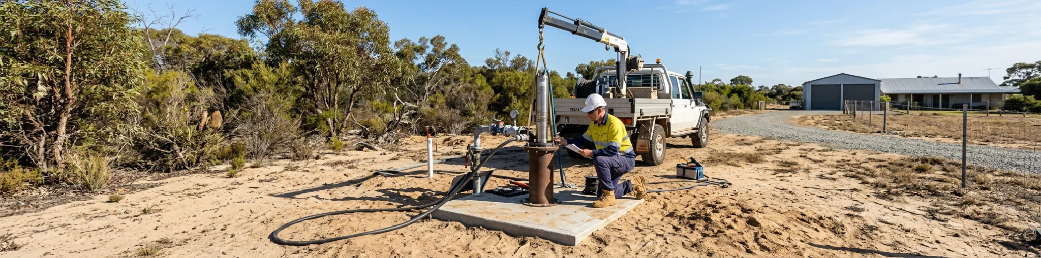
Selecting a bore pump starts with a distinction that is easy to miss: a bore is the water source, while the pump is the machine that must move water through a particular system. They are connected, but one cannot be assumed from the other. A bore may be deep yet have a limited sustainable yield. A pump may be able to produce the required head on its curve, yet be unsuitable for the available water level, bore geometry, water chemistry or motor-cooling conditions.
That is why bore pump sizing Perth work should begin with evidence rather than a nominal pump size, total bore depth or property type. The objective is to define a duty that the source can sustain and the system actually needs, then screen the equipment and installation constraints around it. This approach is relevant to domestic, irrigation, commercial and other groundwater uses, but the final information required will vary with the application.
Perth’s groundwater setting adds another reason to keep the evidence chain clear. The WA Government’s Perth Groundwater Map can help with early planning by indicating the likely watertable depth, the base of the superficial aquifer and indicative groundwater salinity in an area. It is a useful context, not a pump-selection calculation. It cannot confirm the construction, performance or water quality of a particular bore.
Start by separating source capacity from pumping duty
The first question is not “what pump fits the bore?” It is “what water service is required, and what can this bore provide under a representative pumping condition?” Keeping those questions separate prevents a target flow from being treated as evidence of bore yield.
The water requirement should describe how and when water is used. For irrigation, that may mean the zones that can operate together, their flow pattern and the pressure needed at the relevant outlets. For a building or process application, it may mean peak simultaneous demand, the discharge point and the pattern of operation across the day. A tank-filling or transfer duty needs its own flow requirement and receiving-point conditions.
Write down the anticipated operating cases before considering a pump range. Useful questions include:
- What is the required flow at the point of use?
- Which demands can occur at the same time, and which are staged?
- Is the duty intermittent, seasonal, extended or variable?
- What terminal pressure or discharge condition is required?
- Could valves, irrigation zones or future alterations change the operating flow?
This description turns a general request for Perth groundwater pumps into a hydraulic requirement that can be checked. It also exposes conflicts early. A system may ask for a short peak flow that the source should not be expected to deliver continuously. In that case, storage, operating pattern or the wider system concept may need review; fitting a larger pump does not create more sustainable groundwater supply.
Build the bore record before estimating lift
A bore log is one of the most useful starting documents. Depending on the record, it can identify the bore depth, soil composition, yield and an existing pump make or model. It may also help establish the casing and screen arrangement. Pair it with any drilling, development, rehabilitation or previous pump records rather than relying on memory of the installation.
The water-level evidence deserves particular care. Static water level is the level before pumping. Pumping water level is the level observed while the bore is being pumped at a recorded test flow. The difference between them is drawdown. For a lift/head assessment, the pumping level under the intended test condition is generally more informative than total bore depth alone because it reflects where the water level sits while the system is drawing from the source.
That does not make one test result permanent. Yield, drawdown and recovery may vary with the test conditions, the aquifer and the history of operation. Record the test flow, the duration, the measured water levels and the recovery observation, together with the date and any relevant bore condition. A drawdown figure with no test flow or timing behind it is difficult to interpret.
For a structured starting list, APT Water’s bore pump information requirements identify depth, static level, expected drawdown, target flow, pressure, water chemistry, bore construction and power supply among the inputs that matter. The list is valuable because it keeps the bore, duty and installation information together; it does not remove the need to verify those inputs for the individual site.
Establish the system duty at the same flow
Once the water requirement and bore evidence are visible, establish the system duty at the flow being considered. The key pairing is required system flow and total dynamic head, or TDH, at that same duty point. TDH represents the energy the pump must add to overcome the relevant elevation, terminal pressure and losses in the installed discharge system.
For a bore installation, the lift component is tied to the pumping water level and discharge elevation, not simply the full drilled depth. The discharge arrangement then adds its own requirements: pressure at the delivery point, pipe length and internal diameter, fittings, valves, filters or other components, and the operating positions that apply to the selected case. These details can change the head requirement materially, so an assumed pressure or a pipe route sketched from memory is a weak basis for selection.
This is deliberately a high-level sizing step, not a substitute for a full TDH calculation or pipe-loss design. Its purpose is to make sure the duty statement and the source evidence describe the same operating case. If the required flow is changed, friction losses, pumping water level and the bore’s response may also change. Revisit the evidence rather than carrying an earlier head estimate forward unchanged. Only at this point do published submersible bore pump ranges become useful as families to screen against the documented duty and constraints, not as model recommendations.
Put the sustainable-yield ceiling ahead of the pump curve
The pump curve answers a different question: whether a particular pump configuration can provide the nominated flow and head. It does not prove that the bore can sustain that flow. Sustainable yield and drawdown are source constraints, so they remain in force even where a curve indicates more hydraulic capacity.
This distinction matters where a pump is capable of pulling the pumping level down further as demand rises. Operation above what the bore can sustain may produce increasing drawdown, unstable supply or low-flow conditions. It is not resolved merely by choosing a pump with more motor power or by setting a control to request a higher flow.
Protection has a role once the operating limits are understood. APT Water’s low-flow bore pump protection information provides a useful pathway for considering dry-run or low-flow sensing and related protection measures. Such measures can respond to a detected condition or support an operating strategy. They do not establish sustainable yield, replace a pumping test or make an unsuitable duty suitable for the bore.
The broader APT Water information pathway can help place the bore, hydraulic duty, water conditions and installation details in one application context. Commissioning records should then preserve the source evidence used to set the system up. Flow, pressure, drawdown and power recorded at commissioning can provide a baseline for later comparison. If output changes, a comparison is more useful when the original test condition, instrument locations and control state are known. It becomes possible to ask whether the source, system resistance, water condition or equipment behaviour has changed, rather than attributing every change to the pump.
Move from a duty statement to a constrained equipment review
Only after flow, TDH and source limits have been established is it productive to review equipment families. A category page is not a model recommendation. The selection still needs current manufacturer data for the exact pump, motor and application.
At this stage, treat the curve as one screen among several. Check that the nominated duty point and expected operating range are supported by the exact current curve. Then keep the following constraints visible alongside it.
Bore geometry and pump setting
The bore’s internal diameter, casing and screen details affect what can physically be installed and how the pump is set. Total depth does not reveal the internal clearances, screened interval, obstructions or the appropriate setting. The arrangement also needs to account for the pumping water level and the conditions needed around the motor. A pump that fits a nominal bore diameter is not automatically correctly set for that bore.
Motor cooling
Submersible motors need sufficient flow past the motor under the actual installation arrangement. In some configurations, the pumped flow path may not provide that condition and a cooling sleeve or another documented arrangement may be required. This is separate from the system TDH calculation and separate again from source yield. Do not infer cooling adequacy from the fact that the pump is submerged.
Water chemistry and wetted components
The groundwater analysis should be relevant to both the wetted equipment and the downstream use. Indicative salinity from a planning map is not a site analysis, and a material name alone does not prove compatibility. The review can involve the pump, motor, cable, rising main, fasteners, casing and dissimilar-metal interfaces, assessed against exact manufacturer information and the site water data.
Sand or silt observations should also be investigated rather than translated into a universal tolerance. Abrasive material can be a wear concern, but the significance depends on the source condition and exact pump construction. Reduced output, noise or visible particles can be useful evidence to collect; none is a stand-alone diagnosis.
Power, cable and controls
Available power supply, motor and cable requirements, pump setting and the intended control method must agree. A variable-speed control can change the operating point and may serve a particular control objective, but it is not a shortcut around pump-curve, source-yield or motor-cooling checks. Its suitability depends on the equipment, duty profile and documented control arrangement.
Choose protection and records that match the evidence
After the source and duty have been defined, protection should support the identified operating risks. Low-flow or dry-run protection may be relevant where the operating strategy needs to respond to loss of water supply. Controls may also be considered for the required service pattern. The point is not to add features by default, but to document what each measure observes or controls and what it cannot determine.
A practical record set includes the bore log and construction details, pumping-test record, static and pumping levels, flow and drawdown observations, the duty statement, discharge layout, water analysis, power details, pump setting and the exact manufacturer documentation reviewed. Add commissioning values and any future operating changes. This is the evidence trail that allows a later reviewer to understand why a pump was considered and whether the site is still operating on the same assumptions.
It also helps distinguish the checks that are often blended together. TDH is the system-head requirement. The pump curve is a performance check for the specified configuration. Sustainable yield and drawdown describe what the source can supply. Motor cooling is an installation condition. NPSH is a separate hydraulic check and should not be used as a substitute for TDH or bore-yield analysis in a submersible bore-pump discussion.
Bring a complete evidence package to the sizing discussion
The strongest enquiry is not one that asks for a pump from a single dimension. It presents the operating requirement and the evidence needed to challenge it. Before seeking assistance, assemble the end-use flow pattern and simultaneous demand, bore log, casing and screen information, internal diameter, test flow, static and pumping water levels, drawdown and recovery. Include discharge elevation, terminal pressure, pipework, fittings, valves, water analysis, power supply, cable and motor information, plus the proposed pump setting and any control requirement.
If some information is missing, identify that gap rather than filling it with a typical Perth value. A site investigation, pumping test, water analysis or further hydraulic work may be needed before the requirement can be assessed. When you are ready to discuss the evidence, contact APT Water with the bore, duty and water-quality records. That provides a better basis for an application conversation; it does not imply a guaranteed selection, source sustainability or final design approval.
Frequently asked questions
Can a bore pump be sized from bore depth alone?
No. Total depth does not establish pumping water level, sustainable yield, drawdown, required flow, TDH, bore geometry, water chemistry, power or motor-cooling conditions. It is one piece of the bore record, not a sizing result.
What if the pump curve can deliver more than the tested bore yield?
The source constraint still governs sustainable operation. A curve can show hydraulic capability, but it cannot demonstrate that the bore will supply that flow without unacceptable drawdown or low-flow conditions.
Does the Perth Groundwater Map replace a bore log or pumping test?
No. It is a planning indication for items such as likely watertable depth and indicative salinity. A bore log and a documented pumping test provide site-specific evidence needed for a sizing discussion.